| Home |

|
Email: superlumination@cox.net |
 |
|
|
MENU HERE
|
Leds + Flashing Brake Light = Double Safety |
 |
|
Read How LED Stop Lamps Reduce the Number & Severity of Automobile Accidents Read safety studies of flashing brake lights |
|
General Notes: One module can connect to more than one led bulb, but each bulb must be connected to a module in order for that light to flash. In most instances (to avoid running extra wiring) , it is easiest to install one module at each led light (ie: one module on each side of the vehicle). If you have more than one brake light on each side of the vehicle, one module can be used on each side (2 modules for four lights). Important: The FM-00 dual circuit module has the words "FLASHING CONTROL MODULE" molded into the black case. The end closest to the word "FLASHING" must be toward the battery, and the word "MODULE" must be oriented closest to the led bulb. If the module is installed backwards, it will not work. **Operating Voltage: 6 - 13.5 volts Maximum Current : 800ma
Note: These modules are not suited for filament style bulbs. A filament style bulb is not capable of fast switching, and cannot strobe. The power draw of the filament style bulb will destroy the Flashing Modules. |
||||||||||||
|
FLASHING LED CONTROL MODULES The FM-00, FM-01 and FM-02 BRAKER CONTROL MODULES CAN MAKE YOUR led brake lights or reverse lights strobe brightly for a few seconds every time you hit the brakes or switch into reverse. .........After a few seconds the lights stays bright as long as your foot is on the brake or the vehicle is in reverse. The FM-01 and FM-02 BRAKER CONTROL MODULES CAN MAKE any led lights strobe continuously. The FM-03 BRAKER CONTROL MODULES CAN MAKE YOUR led brake lights or reverse lights strobe brightly for a few seconds every time you hit the brakes or switch into reverse. .........After a few seconds the lights stays bright as long as your foot is on the brake or the vehicle is in reverse. The module will then strobe again for 2 seconds when the pedal is first released or when you switch out of reverse. *WORKS WITH ANY LED LIGHTS WORKS GREAT FOR LED BRAKE LIGHT OR REVERSE LIGHT BULB *Note: May not work with some vehicles that modulate voltage to a single circuit bulb for brake indication. Also may not work in some vehicles if the circuit does not completely shut off power when the brake is released.
|
||||||||||||
| Click on images above for larger view | ||||||||||||
| Click Here to view a YouTube video | ||||||||||||
| Click Here for Detailed Operation & Installation Instructions | ||||||||||||
|
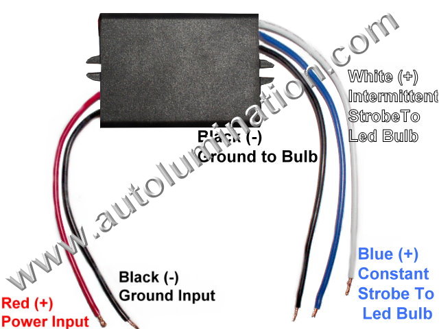
Dual Function: White Wire: Strobes for 2 seconds When you First Brake or Switch into Reverse. Blue Wire: Strobes Constantly |
Single Function: Strobes When you First Brake and Again When you Release the Brake |
Dual Function: White Wire: Strobes for 2 seconds When you First Brake or Switch into Reverse. Blue Wire: Strobes Constantly |
Single Function: Red Wire: Strobes for 2 seconds When you First Brake or first shift into reverse. |
Single Function: Blue Wire: Strobes for 2 seconds When you First Brake or first shift into reverse. |
||||||||
|
 |
 |
 |
 |
||||||||
| FM-02A (10 Hz) FM-02B (20 Hz) | FM-03A (10 Hz) FM-03B (20 Hz) | FM-01A (10 Hz) FM-01B (20 Hz) | FM-00 (20 Hz) Miniature Module | FM-04 (20 Hz) | ||||||||
| With Continuous or Intermittent Strobe Modes | With Intermittent Strobe Mode on Brake and Release | With Continuous or Intermittent Strobe Modes | With Intermittent Strobe Mode on Brake | With Intermittent Strobe Mode on Brake or Reverse | ||||||||
|
Universal Compact Two Function Strobe Module
Only 1-3/4" x 1-3/8" x 1"
|
Universal Compact Strobe Module
Only 1-3/4" x 1-3/8" x 1"
|
Universal Two Function Strobe Module 3-3/8"x 2"x 7/8"
|
Dual Compact Circuit Braker Module 2"x 1"x 3/8"
|
Dual Compact Circuit Braker Module 2-3/4"x 1-1/2"x 1" |
||||||||
|
$9.99 EA |
$9.99 EA |
$8.99 EA |
$ 5.99 EA |
$ 6.99 EA |
||||||||
|
Uses:
Common Applications:
Make any led bulbs or lights strobe continuously. Function: The FM-02 module contains a chip that will cause an led light bulbs to operate as follows (Note: Use either the White wire or Blue wire not both):
Function 1 (If you use the White Wire) 1. Each time power is applied to the red wire, from the battery, the white wire to the led bulb will cause the led bulb to perform a sequence as follows; A. The led will strobe brightly for a few seconds and then stop strobing. B. After a few seconds of strobing, the led light will light bright in a constant-on mode for as long as power is continually applied to the circuit (ie: as long as the brake pedal is pressed). *C. When power is cut to the brown wire (ie: the brake pedal is released, the bulb will go dim.
*Note 1: In a singe circuit bulb such as an 1156 or 921, there is no dim circuit, so the module will sequence whenever the brake is applied, but there will be no dim function.
Function 2 (If you use the Blue Wire) 1. Each time power is applied to the red wire, from the battery, the blue wire to the led bulb will cause the led bulb to strobe continuously until power to the red wire is off.
*Note 1: In a singe circuit bulb such as an 1156 or 921, there is no dim circuit, so the module will sequence whenever the brake is applied, but there will be no dim function.
**Note 2: This module can also be used in a positive
ground 6 or 12 volt electrical system.
|
Uses:
Common Applications:
The FM-03 module contains a chip that will cause an led light bulbs to operate as follows:
1. Each time power is applied to the white wire, from the brake circuit, the led bulb will perform a sequence as follows; A. The led will strobe brightly for a few seconds and then stop strobing. B. As long as power is still applied from the white-blue brake wire, the led light will light bright for as long as power is continually applied to the circuit (ie: as long as the brake pedal is pressed). * B. When power is cut to the white wire (ie: the brake pedal is released, the bulb will flash again for 2 seconds and then go dim.
* Note: In a singe circuit bulb such as an 1156 or 921, there is no dim circuit, so the module will sequence whenever the brake is applied, but there will be no dim function.
**Note 2: This module can also be used in a positive ground 6 or 12 volt electrical system. |
Uses:
Common Applications:
Make any Led bulbs or lights strobe continuously. Function: The FM-01 module contains a chip that will cause an led light bulbs to operate as follows (Note: Use either the White wire or Blue wire not both):
Function 1 (If you use the White Wire) 1. Each time power is applied to the red wire, from the battery, the white wire to the led bulb will cause the led bulb to perform a sequence as follows; A. The led will strobe brightly for a few seconds and then stop strobing. B. After a few seconds of strobing, the led light will light bright in a constant-on mode for as long as power is continually applied to the circuit (ie: as long as the brake pedal is pressed). *C. When power is cut to the brown wire (ie: the brake pedal is released, the bulb will either go dim.
*Note 1: In a singe circuit bulb such as an 1156 or 921, there is no dim circuit, so the module will sequence whenever the brake is applied, but there will be no dim function.
Function 2 (If you use the Blue Wire) 1. Each time power is applied to the red wire, from the battery, the blue wire to the led bulb will cause the led bulb to strobe continuously until power to the red wire is off.
*Note 1: In a singe circuit bulb such as an 1156 or 921, there is no dim circuit, so the module will sequence whenever the brake is applied, but there will be no dim function.
**Note 2: This module can also be used in a positive ground 6 or 12 volt electrical system.
|
Uses:
Function: The FM-00 module contains a chip that will cause an led light bulb or any 12 volt led light to operate as follows:
1. Each time power is applied to the brown wire, from the battery, the black wire to the led bulb will cause the led bulb to perform a sequence as follows; A. The led will strobe brightly for a few seconds and then stop strobing***. B. After a few seconds of strobing, the led light will light bright in a constant-on mode for as long as power is continually applied to the circuit (ie: as long as the brake pedal is pressed). *C. When power is cut to the brown wire (ie: the brake pedal is released, the bulb will go dim.
*Note 1: In a singe circuit bulb such as an 1156 or 921, there is no dim circuit, so the module will sequence whenever the brake is applied, but there will be no dim function.
**Note 2: This module can also be used in a
positive ground 12 volt electrical system.
*** Note 3: The FM-00 has a built in circuit that will temporarily suspend the strobing effect if the brake pedal is pressed repeatedly. The strobe chip sill only reset if the brake is released for about 5 seconds or more. |
Uses:
7507, 1156,3156, 7440, 921 single circuit bulbs & 7225, 1157, 3157, 7443 dual circuit bulbs, or use with any led light bulb or led fixture. **Can be used in any 6 or 12 volt (-) ground or (+) ground systems Common Applications: Brake light Warning Strobe Reverse Light Warning Strobe Function:
The FM-01 module contains a chip that will cause an led light bulb or any 6 or 12 volt led light to operate as follows:
1. Each time power is applied to the brown wire, from the battery, the black wire to the led bulb will cause the led bulb to perform a sequence as follows; A. The led will strobe brightly for a few seconds and then stop strobing. B. After a few seconds of strobing, the led light will light bright in a constant-on mode for as long as power is continually applied to the circuit (ie: as long as the brake pedal is pressed). *C. When power is cut to the brown wire (ie: the brake pedal is released, the bulb will either go dim.
*Note 1: In a singe circuit bulb such as an 1156 or 921, there is no dim circuit, so the module will sequence whenever the brake is applied, but there will be no dim function. **Note 2: This module can also be used in a positive ground 12 volt electrical system. If you have a (+) positive ground volt system, The module must be installed inline in the (+) Ground wire and the blue wire must be installed toward the led light or bulb. The brown wire must be installed toward the bulb. |
||||||||
|
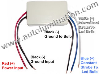
Installation: Install the module anywhere between the battery power and the led light that you wish to make flash. Connect the wires as follows: Connect the flashing module in the wires feeding to any led bulb as follows: White Wire - Connect to the (+) side of any led light(s) that you want to strobe intermittently for the first 20 ms). Red Wire - Connect to (+) Wire on the Power or Battery Side. Black Wires - Splices into to the - ground wires on both sides. Blue Wire - Connect to the (+) side of any led light(s) that you want to strobe continuously.
Note 1 : You do not have to use both the white wires and the blue wires at the same time. You can and normally would use one or the other.
****WARNING**** Never allow any of the bare wires connected to the module to touch together if power is connected to the module. This can instantly and permanently damage the module. |
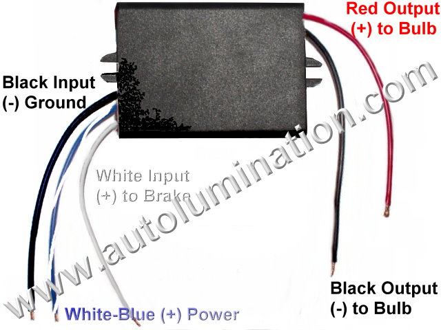
Installation: Install the module anywhere between the battery power and the led light that you wish to make flash. Connect the wires as follows: Connect the flashing module in the wires feeding to any led bulb as follows: * Blue Input Wire - Connect to the (+) battery power to power the module. White Input Wire - Connect to (+) Brake Circuit. Black Input Wire - Connect to the - ground wire. Red Output Wire - Connect to the (+) side of any led light(s) or Bulb(s). Black Output Wire - Connect to to the - ground wire going to the led light.
* Note: You must connect the blue wire to a 12+ constant-on circuit. This circuit must have + power on after the brake pedal is released of the light will not flash when the brake pedal is released.
****WARNING**** Never allow any of the bare wires connected to the module to touch together if power is connected to the module. This can instantly and permanently damage the module.
|
Installation: Install the module anywhere between the battery power and the led light that you wish to make flash. Connect the wires as follows:
Connect the flashing module in the wires feeding to any led bulb as follows: White Wire - Connect to the (+) side of any led light(s) that you want to strobe intermittently for the first 20 ms). Red Wire - Connect to (+) Wire on the Power or Battery Side. Black Wires - Splices into to the - ground wires on both sides. Blue Wire - Connect to the (+) side of any led light(s) that you want to strobe continuously.
Note: You do not have to use both the white wires and the blue wires at the same time. You can and normally would use one or the other.
****WARNING**** Never allow any of the bare wires connected to the module to touch together if power is connected to the module. This can instantly and permanently damage the module. |
Installation: The FM-00 module can be used in conventional (-) ground systems and (+) ground 12 volt systems. It will not work in 6 volt systems. Install the module anywhere between the battery power and the led light that you wish to make flash. Connect the wires as follows: Connect the flashing module in the wires feeding to any led bulb as follows: Important: The dual circuit module has the words "FLASHING CONTROL MODULE" molded into the black case. The end closest to the word "FLASHING" must be toward the battery, and the word "MODULE" must be oriented closest to the led bulb. If the module is installed backwards, it will not work. Power must flow thru the module and then to the led lights or bulbs that you want to make flash. Red Wires - Connects to the (+) brake light wire. Black Wires - Connects to the (-) ground wire.
****WARNING**** Never allow any of the bare wires connected to the module to touch together if power is connected to the module. This can instantly and permanently damage the module. |
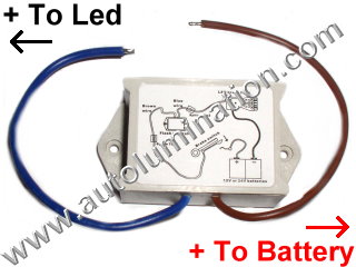
Installation {Conventional (-) ground system} : Install the module anywhere between the battery power and the led light that you wish to make flash. Connect the wires as follows: Connect the brown wire to the wire coming from the (+) battery side of the circuit. Connect the blue wire to the (+) wire going to the led light or light bulb. Installation {Positive (+) ground system} : Install the module anywhere between the battery power and the led light that you wish to make flash. Connect the wires as follows: Connect the blue wire to the wire coming from the (+) battery side of the circuit. Connect the brown wire to the (+) wire going to the led light or light bulb. ****WARNING**** Never allow any of the bare wires connected to the module to touch together if power is connected to the module. This can instantly and permanently damage the module. |
||||||||
|
Operating Voltage: 11.5 - 13.5 volts Maximum Current : 800ma Note: These modules are not suited for filament style bulbs. A filament style bulb is not capable of fast switching, and cannot strobe. The power draw of the filament style bulb will destroy the Braker Flashing Modules. |
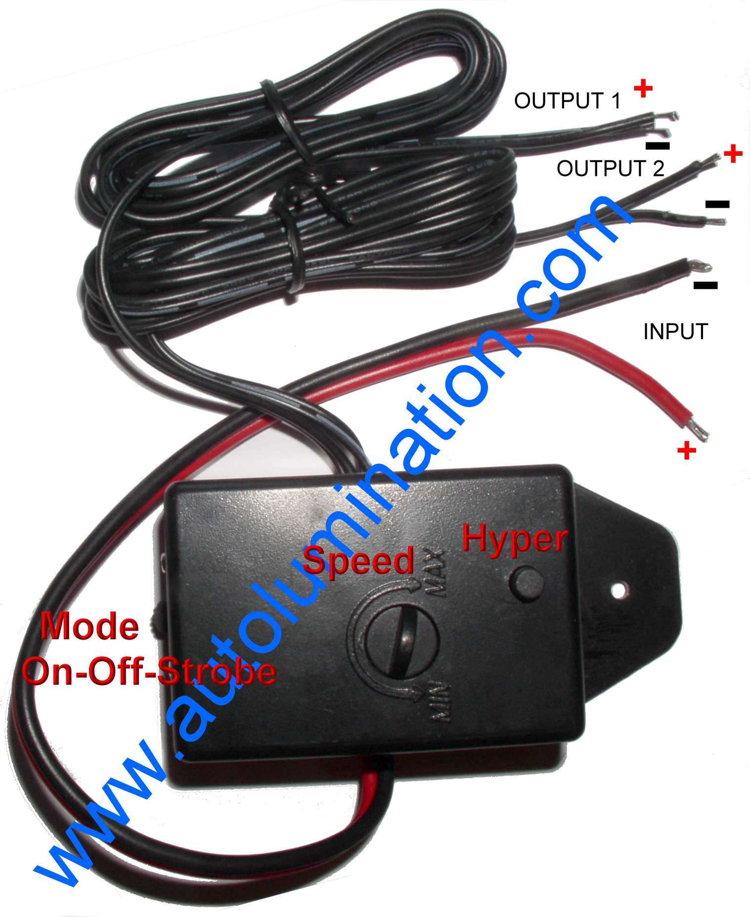
![]() 2 Circuit 12 Volt LED WIG WAG Safety Strobe Controller
2 Circuit 12 Volt LED WIG WAG Safety Strobe Controller
![]()
Strobe rate is adjustable from 1 flash per second up to 3 flashes per second on each side.
Strobe sequence Wig WAG alternates (2 flashes left followed by 2 flashes right) between the right tube & left tube
With rubber grommet for installation in a 5/8" hole
For use with any led bulbs or led lights we sell
Turns any led bulbs or lights into an instant emergency flasher/ warning system

|

|
|
Click on images above for larger view |
|
|
Note: This truck is outfitted with our 3157 48 LED SMT Bulbs + Led WIG-WAG Controller |
|
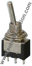
| Manual On/Off Switch (Optional) |
Connects to 12 volts |
| $19.99 With Manual Switch | $17.99 No Switch |


